Custom Bases
Introduction
The push button switch is designed so that custom bases for different use cases can be created. It is hoped that the community will share these with each other through sites like Printables, Thingiverse and GitHub.
The instructions below are meant to help get someone started creating their own switch bases. A willingness to learn, as well as access to a 3D printer and CAD software such as FreeCAD, TinkerCAD or Fusion360 is all that is needed. If you have comments or questions, please feel free to join the mailing list.
Base Dimensions
Bases can be designed in any way, but some sample dimensions are given for the straight base that is included with the design.
The straight base has the same diameter as the switch bottom, with no overhang. This means that the base is 75mm in diameter, or 37.5mm in radius. Other dimensions can be used if overhang is desired, which is the case with the flange base.
The bottom of the push button switch has 3 holes in a pattern, with captive nuts on the opposite side (assuming that they were installed by the builder). The following sketch shows how the holes are laid out in a base to match.

What this sketch means in words is that the hole pattern can be laid out in a polar (aka radial or circular) pattern every 120 degrees, with a pattern radius of 22.5mm. If the holes are laid out this way, they should mate properly to the switch bottom. If your base has an orientation to it, be sure that when installed the base and the cable cutout on the switch body will be aligned properly. If it does not fit your intention, you can shift the starting angle of the array by any value needed to make the base and the switch cable cutout align properly.
Relief Areas
Depending on the screws used, 3D printer accuracy, and amount of torque applied to the screws, they may protrude below the surface of the switch bottom slightly. It is best to provide some open area between the base and the switch bottom. The inside of the straight base is shown below as an example.
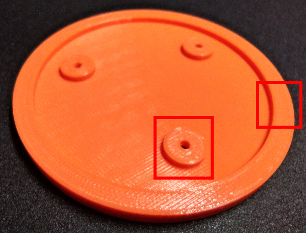
Notice that there is a lip around the outside of the base (highlighted on the right side), that has an outside diameter of 75mm and an inside diameter of 65mm. This lip is the full base thickness of 5mm. There are also 3 bosses (one of them is highlighted in the image) at each of the mounting hole locations. Each of these bosses is the full 5mm thick as well. This provides an open relief area under the switch, and also saves on print material and time.
Wrapping Up
If your base is a different thickness than 5mm, you will most likely need to use a different screw than the M2x8mm socket head screw that is specified in the assembly documentation. Don't be afraid to deviate and try different design options in order to best fulfill your needs. Also, please do not hesitate to share your base designs with the community so that everyone can gain benefit from your efforts.