
Mechanical - Push Button Switch Documentation
Contents
In order to produce the mechanical parts for the push button switch, all plastic parts must be 3D printed and then captive nuts must be installed in the prints. The sections below walk through each of these steps.
Print Parts
Step 1: Download STL FilesA zip file of all STL files needed to print the switch must be downloaded, and are available here. Once that file has been downloaded and the STLs have been extracted, the parts can be printed.
Step 2: Print SettingsFor reference, the parts pictured in this document were printed on a Prusa i3 Mk2 with a 0.4mm nozzle. Both PLA or PETG types of filament have been used to print these parts. PETG will produce more durable parts but is not required. All parts are designed so that the larger flat surface should be placed on the print bed.
- _Supports:_ No
- _Brim:_ Yes (mainly with PLA for bed adhesion)
- _Layer Height:_ 0.2mm
- _Infill:_ 20% (higher infill may increase durability)
- _Perimeters:_ 4 (increased from 2 for greater durability)
The following is the list of parts that should be in the zip file. These are standard STL files that should work with any 3D printer and/or slicing software.
- band_mounts.stl
- switch_stem.stl
- switch_cap.stl
- switch_body.stl
- switch_bottom.stl
Clean Up Parts
The parts should be ready to assemble. However, there is sometimes extra plastic in the holes, nut traps, or counter-bore holes. These areas should be cleaned up before adding the captive nuts and doing the assembly steps.
Extra Plastic in Counter-BoreBelow is an example of a counter-bore hole with an extra plastic string in it. This extra plastic will keep the bolt from seating properly in the bottom of the hole and must be removed.
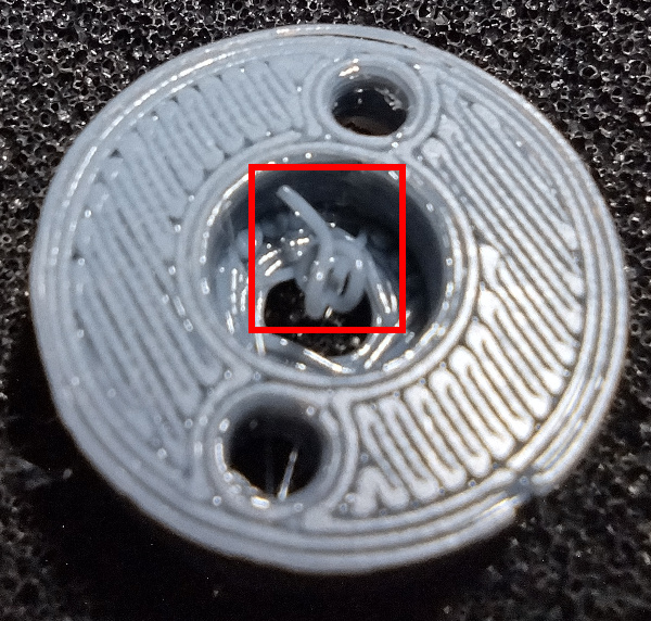
Most plastic strings are easy to remove with tweezers. The string in the picture above can be removed by grabbing it with the tweezers and twisting.
Non-Round HoleMost of the time there is no issue with the roundness of a printed hole, but sometimes the hole is out-of-round enough that it will not let a bolt pass through.
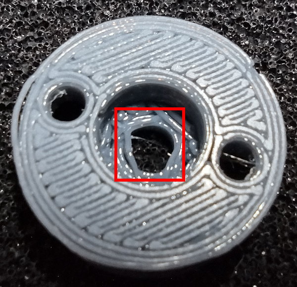
In this case, a drill bit can be used to clean up the hole. Be careful not to force a drill bit that is too large through the hole, or the size tolerance of the hole may be altered too much. If using a power drill with the drill bit, be careful not to damage the hole by enlarging it or making it an oval shape.
Extra Plastic in Nut TrapCaptive nuts are used throughout this design instead of heatset inserts or simply threading screws into the plastic. This ensures a durable design without the complications that using heatset inserts can cause.
Sometimes there is excess plastic inside the nut pockets which can prevent the nuts from pulling all the way down into the pocket. This should be cleaned out with tweezers.
Add Captive Nuts
This switch design uses captive nuts instead of threading screws directly into the plastic, or using heatset inserts. Threading screws directly into plastic, even if the plastic is tapped, makes for a weak connection because the plastic threads strip out easily. Heatset inserts create a very strong connection, but are hard to install squarely into a hole, and tend to cause distortion of the plastic around the insertion site, such as mounding.
The M2 nuts will be pulled down into their pockets in this step so that the assembly step can happen more smoothly later.
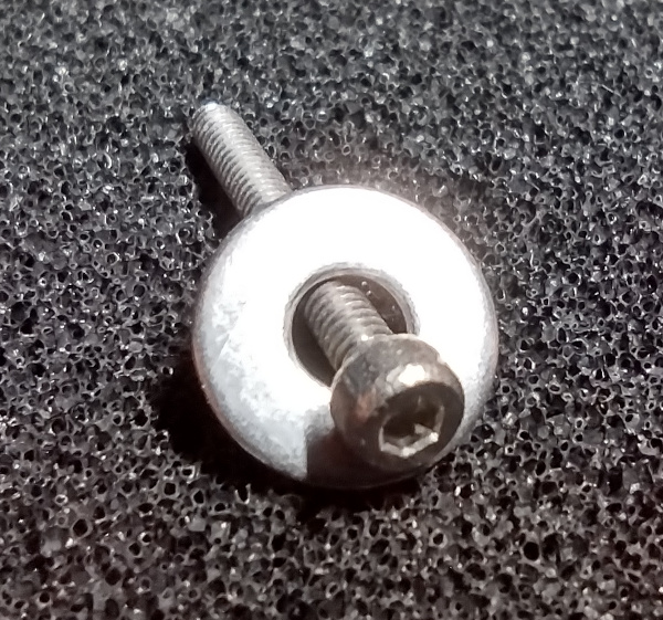
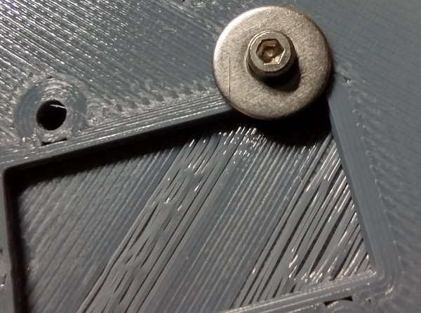
Step 1: Prepare the Puller ScrewA longer M2 screw is used to pull the M2 nuts squarely into their pockets. An M2x16 Socket Head Screw can be used to pull the M2 nuts squarely into their pockets. The screw should be paired with an M2 Washer so that the head does not indent the plastic under it while the nut is being pulled into position.
 Step 2: Install the PCB Captive Nuts
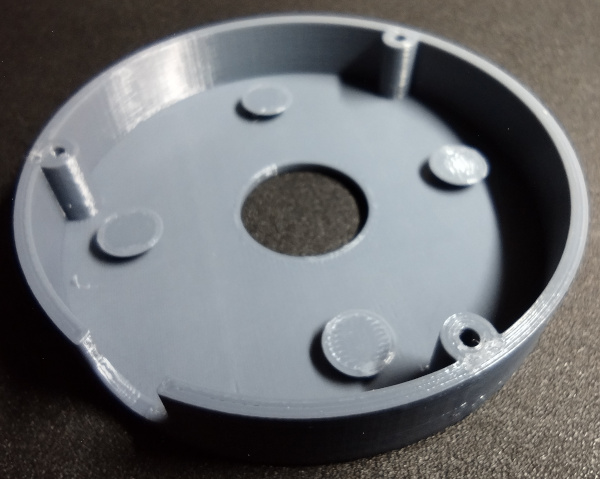
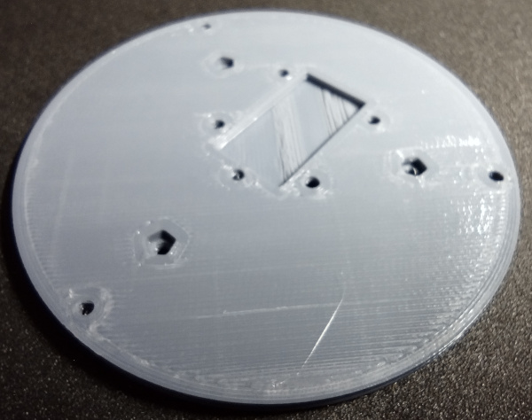
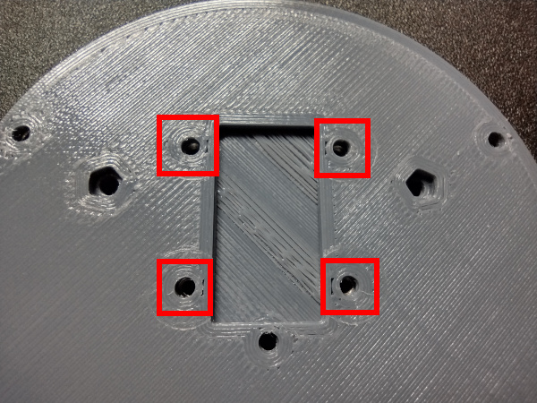
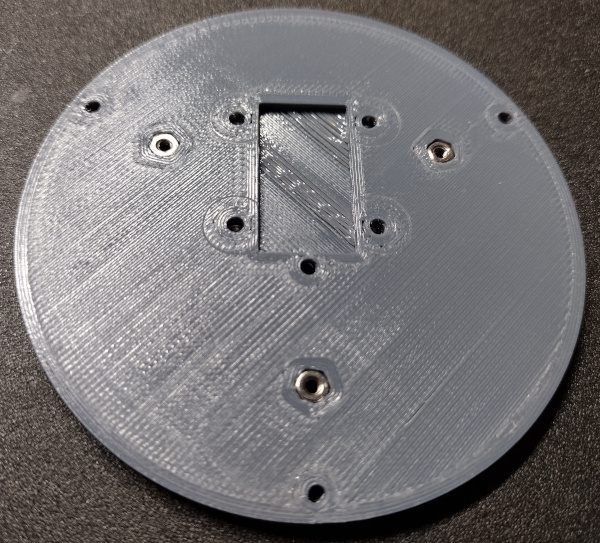
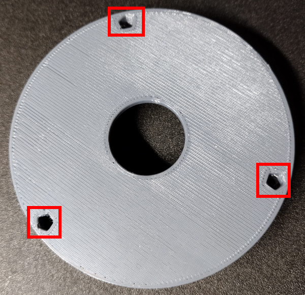
There are 4 nuts that will be used to hold the PCB (printed circuit board) in place. The locations of these nut pockets are in the bottom side of the bottom part of the switch, and are shown in the following image.
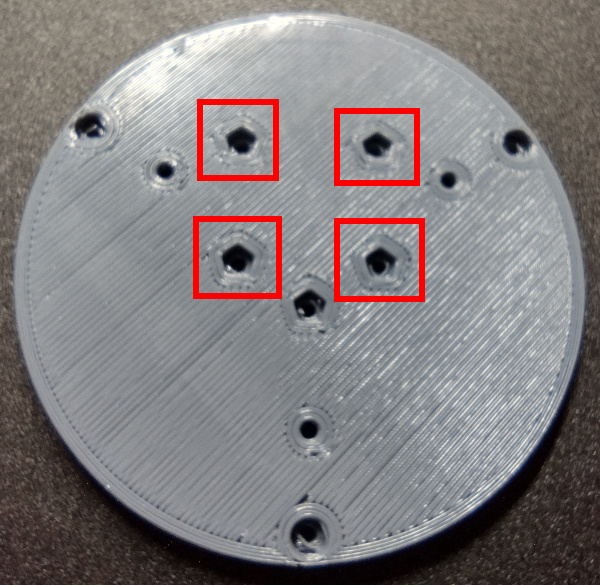
Below are the same holes viewed from the top side.
Insert the nut puller screw through the top side of the bottom part, and thread an M2 hex nut onto the end. Thread the nut on until it comes in contact with the pocket.
WARNING: Do not over-tighten the nuts in this step. Too much torque can cause the nuts to spin in their pockets, which will strip the plastic out so that the pocket will no longer hold the nut captive. Ensure the top face of the nut is at, or a little below, the surface of the plastic when it is drawn down with the puller screw.
Now take a 1.5mm Hex Wrench and tighten the puller screw until the captive nut is seated in the pocket. Make an effort to keep the points of the nut aligned with the points of the pocket. This often happens naturally as the screw is tightened. Continue tightening the screw until the nut has obviously bottomed-out in the pocket, or the nut is at or below the surface.
Once this first nut has been installed, remove the puller screw and seat the remaining three nuts in their respective pockets.
NOTE: If the M2 nut is too large for the pocket, there is not an easy work around. The best options are to buy M2 nuts that are the proper size, or download the source CAD model for the switch bottom and modify the captive nut pocket size.When all captive nuts are installed, the bottom should look something like this.
Step 3: Install the Mounting Base Captive Nuts
There are three holes in the switch bottom which will be used later to attach a mounting base. The intention is for these bases to be designed and printed for each use case. Examples might be a v-block base for mounting the switch to a metal tube, or a flat base with pockets where double stick tape can be applied.
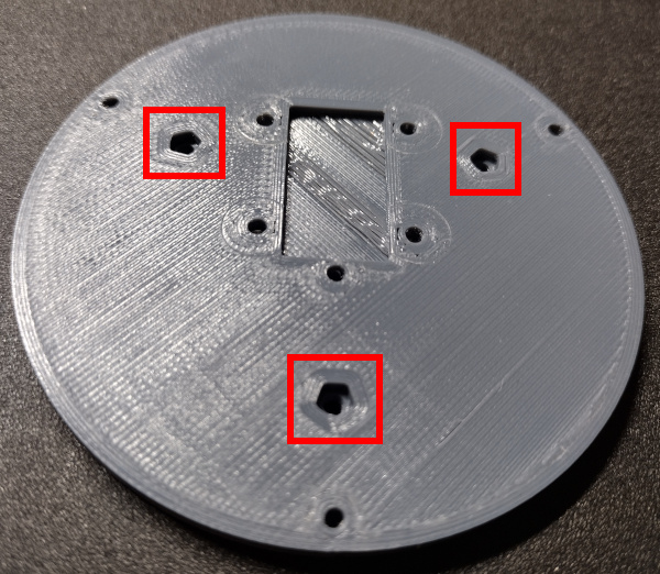
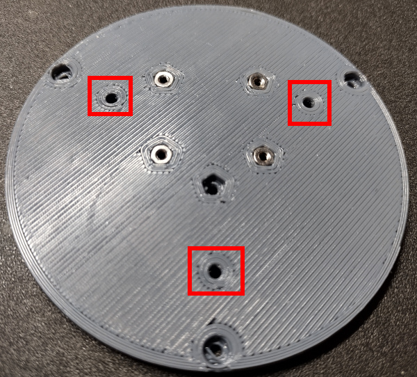
The three mounting base captive nut pockets are highlighted below.
And here are the same hole locations when viewed from the bottom side.
WARNING (Again): Do not over-tighten the nuts in this step. Too much torque can cause the nuts to spin in their pockets, which will strip the plastic out so that the pocket will no longer hold the nut captive. Just make sure the top face of the nut is at, or a little below, the surface of the plastic.
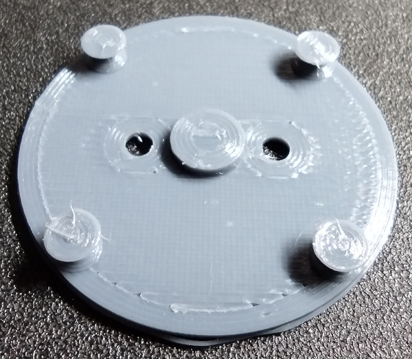
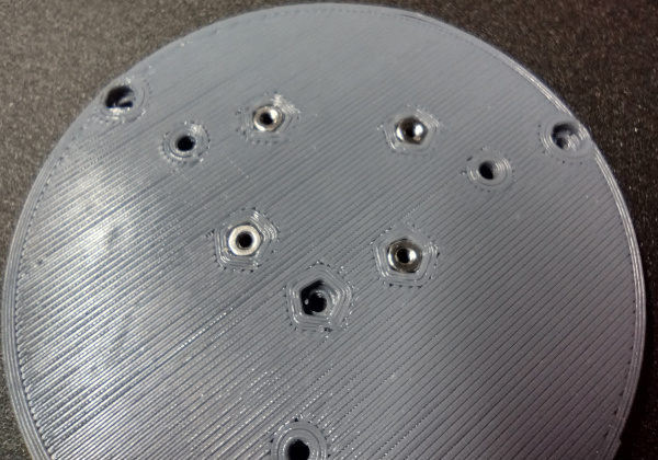
Repeat the same process with the puller screw that was used in Step 2, and pull each M2 Captive Nut down into their pockets. When finished, the switch bottom should look like the following when viewed from the top side.
Installation of the captive nuts in the switch bottom is now complete.
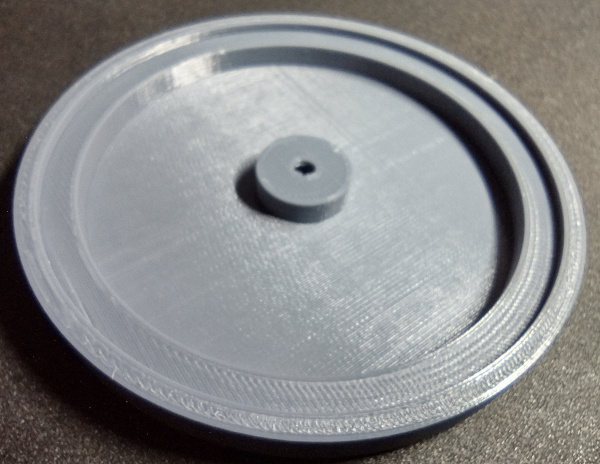
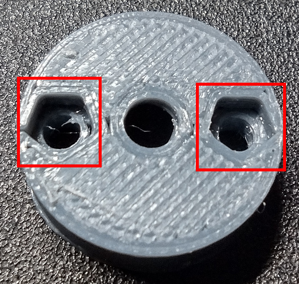
Step 4: Install the Stem Mounting NutsThere are two holes in the switch stem that hold the rubber band mounts in place. The locations of the nut traps for these holes is shown in the following picture.
Install each M2 captive nut as in steps 3 and 4 (as always) being sure not to over-torque the nuts. When finished, the stem should look like the following.
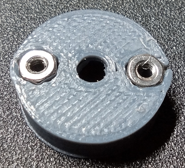
Notice that there can be a little deformation at the edges of the stem from where the nuts are pressed in. This is acceptable as long as the deformation is around the outside edge, and not on the top or bottom surface of the stem.
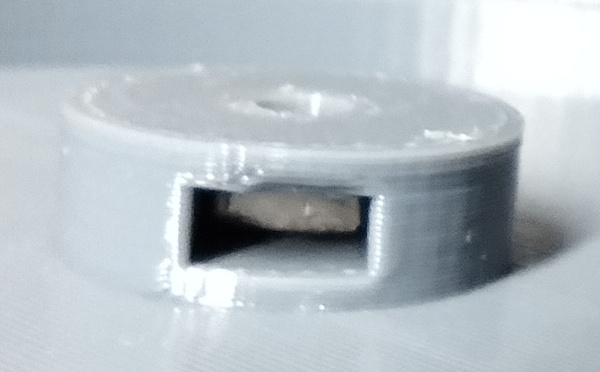
Step 5: Install Body Captive NutsThere are three captive nuts that need to be installed in the switch body, and those will be used to attach the bottom during the final assembly process. The locations of each of the holes are highlighted in the following image.
Pull an M2 Captive Nut down into each of these pockets using the puller screw technique and the 1.5mm hex wrench that has been used in other steps. These pockets are deeper than any of the others, and the nuts need to be pulled down to the bottom of each pocket to work correctly during final assembly.
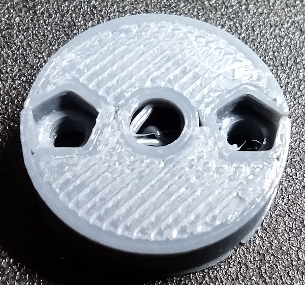
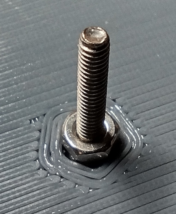
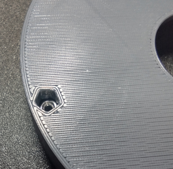
The nut should measure about 4mm from its top to the top of the switch body. The following image shows how deep one of the nuts looks in the pocket.
Step 6: Install Square Captive Nut
There is one last captive nut to install, and that is in the switch cap. The location is shown in the following image.
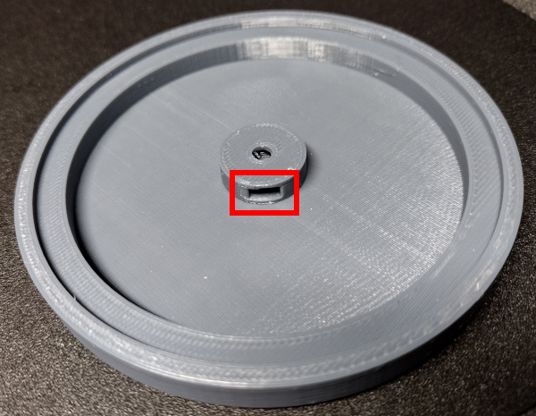
The M3 square nut can be inserted into the pocket with fingers or tweezers. A set of curved tip tweezers makes insertion easier. Be sure to push the nut all the way down into the pocket so that the threaded hole in the center of the nut lines up with the hole in the switch cap. Pushing with a pair of tweezers or a small L-shaped hex wrench can help.
If the nut will not seat all the way down into the pocket, there may be a bit of plastic in the pocket. The square nut can be removed with tweezers by placing the tips down in the center hole and pushing the nut towards the pocket opening. Then any extra plastic should be cleared from the pocket with tweezers.
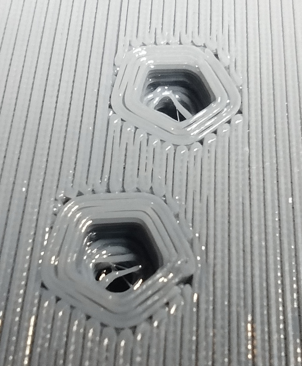
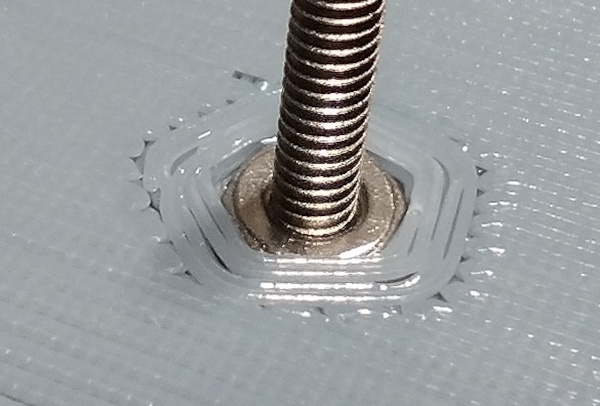
The next images show the square nut properly installed in the switch cap.
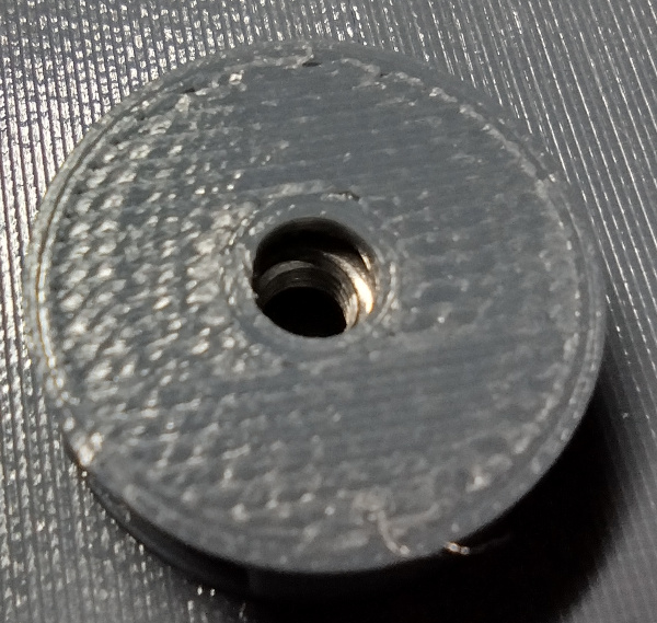
After that square nut is installed, it is now possible to move on to final assembly.
© 2018-2026 7B Industries